2 System Structure Flow Design Our entire system needs to complete functions such as distance measurement, speed measurement, positioning, and control of car movement. The system includes the following six parts: ultrasonic transmission circuit, ultrasonic receiving circuit, signal processor, temperature measurement, car control circuit, etc. Five parts. System structure diagram shown in Figure 1:
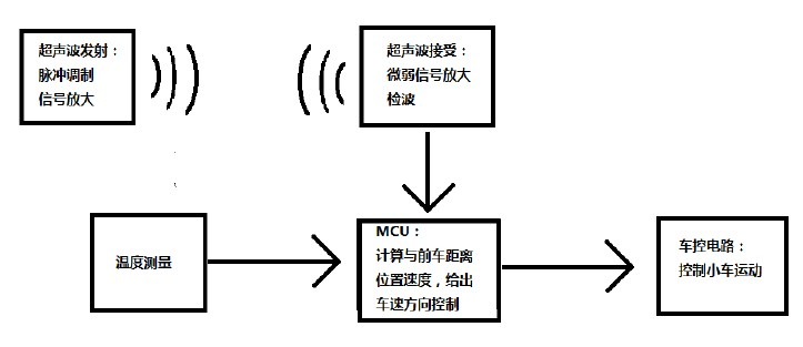
Figure 1: System block diagram
The specific hardware consists of: MCU adopts AT89S52 single-chip microcomputer, P1.0 port outputs 40K square wave signal required by ultrasonic transducer, drives the sensor after inverter 7404, in order to enable the ultrasonic wave to launch farther, we pick up The three transmitters use external interrupt 0 to monitor the return signal output from the ultrasonic receiver circuit. The echo detection uses infrared detection integrated chip CX20106. The display circuit uses a simple 4-bit common-yang LED digital tube, and the code is 74LS244 for bit-code. 8550 driver. The temperature measurement section uses 18B20 to measure the current ambient temperature to determine the speed of ultrasonic propagation.
3 MCU algorithm control 3.1 distance calculation and position judgment SCM can calculate the time between transmitting and receiving ultrasonic, according to the actual temperature measurement system to find out the sound speed at the corresponding temperature, calculate the reflector distance from the two receivers distance. Theoretically, the spatial position of the object can be derived directly from the above two data (as shown in Figure 2 and Formulas 1 and 2).
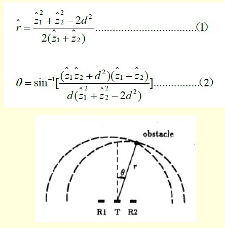
Figure 2 Spatial orientation of ultrasonic sensors

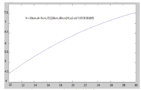
Figure 3z2-z1 and l relationship
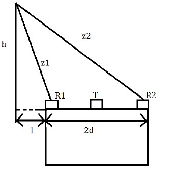
Figure 4 The geometric relationship of each physical quantity
3.2 Speed ​​Calculation Speed ​​We use a simple approximation to estimate the distance. We can calculate the distance between the system's ranging distances to be about 120 ms. By comparing the current ranging result with the previous ranging result, we can estimate according to formula 7 Approximate current speed:
3.3 System Flow (see Figure 5).
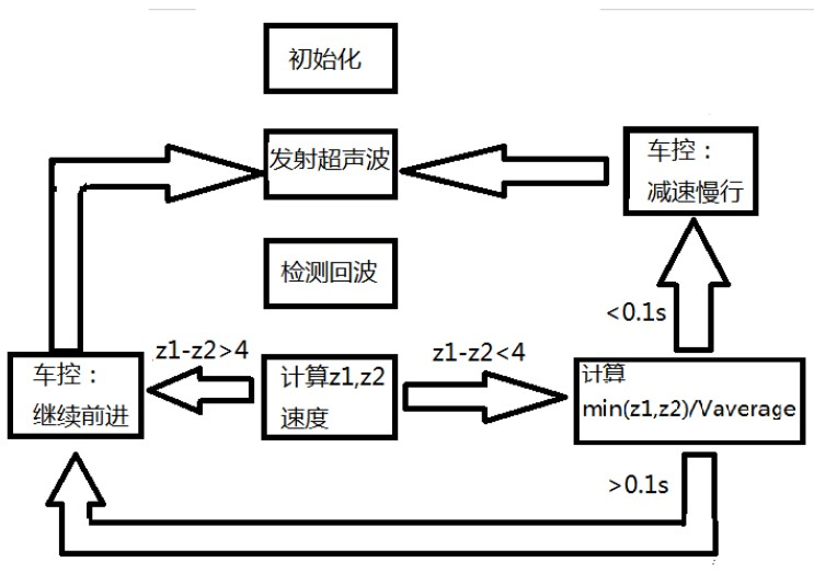
Figure 5 system flow
Table 1 Ranging results
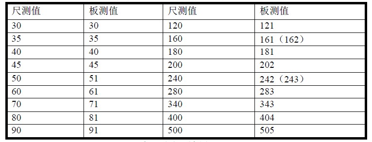
From this table we can see that our ranging circuit is very accurate.
Figure 6 shows our test results for the dual head solution:
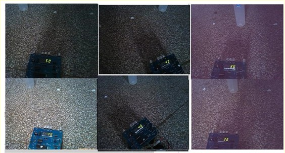
Figure 6 dual receiver head test results
Finally, after we completed the debugging of the entire car system, we used it to test and found that whether it is a moving or stationary obstacle, the car can accurately judge whether to move forward or stop at any position in front of the car.
5 conclusions In summary, this system proposes an on-vehicle automatic speed measurement and ranging control system based on dual ultrasonic receivers and 3 transmitters, which can effectively play a role of pre-judgment for driver protection, etc. When the driver is driving When an emergency control measures are taken in case of an emergency, the system can also be forced to correct or alert the driver to check. Because the system is simple, economical and stable, it has a very large market prospect.
GJCNC-BP series CNC busbar punching & shearing machine is the computer-controlled equipment of high efficiency and high precision, specially used for busbar processing; Dies of punching, shearing are placed together in the storeroom of dies; It is capable of executing punching(round, oblong and other holes), shearing, slotting, round cornering and other processes; Automatic clamp switching can be achieved without manual intervention for longer busbars. Finished work pieces will be sent out through the conveyor. Such machine series can be used in combination with the CNC Busbar Bending Machine to form an assembly line of busbar processing.
Turret Punching Machine,Busbar Punching Machine,Cnc Turret Punching Machine,Servo Punch Machine
JINAN EURO-ASIA MACHINERY CO., LTD , https://www.euroasiamachine.com
