With the gradual strengthening of environmental awareness, countries around the world are competing to develop environmentally-friendly vehicles. China is also investing in the development of battery-powered electric vehicles. The indispensable instrument for electric vehicles is the battery capacity meter. Just like the fuel gauge of an ordinary car, it tells the user how much capacity the battery still has and how many kilometers it can travel. In fact, not only electric vehicles require battery capacity meters, but many applications where batteries are used are urgently required. The traditional means of monitoring the battery is only a voltmeter, but the voltage can not accurately reflect the capacity of the battery, and the voltage is normal, but there is no capacity. As users are often confused, I don't know how long the battery can be used, so it affects the use of many key occasions, and it is easy to cause accidents. Therefore, it is necessary to develop an instrument that reflects the battery capacity. At present, similar products have been introduced in foreign countries, but due to the reasons of technical confidentiality, no method for introducing them has been introduced.
In this paper, an electric vehicle is used as a target, and a battery capacity meter realized by a power metering method is proposed, which can measure the battery capacity under certain conditions. It is based on the principle of calculating the battery charging energy and releasing energy and multiplying the corresponding loss factor to indicate the capacity of the battery (the coefficient should take into account the charging efficiency and the battery discharge current and other factors on the battery capacity). influences).
Basic principle of battery capacity meter
In addition to some of the factors of the battery itself, the capacity of the battery depends mainly on the amount of charge and the amount of discharge. Obviously, if the charge and discharge of the battery can always be recorded, the capacity can be measured. We envision a device called a battery capacity meter on a conventional single battery to achieve display capacity. The capacity meter dynamically monitors the sum of the battery charge and discharges the total power and visualizes it after calculation. Other factors affecting the battery capacity are combined into a loss factor, which is multiplied by the charge and discharge amount and is the remaining battery capacity. Since the type, size and performance of the battery are not the same, the loss factor is not the same, and it is mainly obtained by experiment. Therefore, the coefficient problem is not discussed here, and only the circuit that completes the function of measuring the electricity is studied.
There are many ways to charge and discharge the battery, such as constant current, voltage limiting, pulse, negative pulse, etc., so simply multiplying the current by the time to measure the capacity can not adapt to other ways than constant current, and the integration method can not adapt to negative The need for pulse charging, while it requires time parameters, is also not suitable. Obviously, the design of the battery capacity meter should meet most of the charging and discharging methods. Regardless of the charging method, the key parameters affecting the battery capacity are current and time, and in the case of negative pulse charging, there is only a negative current at the same time. To this end, we have designed the battery capacity meter circuit of the following working mode. The principle block diagram is shown in Figure 1.
Firstly, the battery charge and discharge current is monitored, converted into a voltage signal, amplified, sent to a voltage frequency converter to become a frequency signal, and finally sent to the counter to record the number of pulses, and the count value is displayed by a certain method. It constitutes a battery capacity meter. In fact, the frequency of the frequency represents the magnitude of the current, the current is large and the frequency is high, and the number of pulses recorded at the same time is greater, and vice versa. The charging and discharging time is also reflected in the counting of the pulses, and the counting time is longer than the counting. In this way, the calculation of the charge and discharge amount of the battery is completed by the counting method.
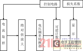
Figure 1 battery capacity meter block diagram
The combination of the absolute value amplifier and the reversible counter realizes the measurement of the discharge gap (ie, the negative pulse charge) during charging, and simultaneously calculates the charge and discharge directions in one set of circuits. Positive counting during charging, reverse counting (subtraction) during discharging, and controlling the counting direction of the reversible counter by the flow direction of the current.
Program demonstration and technical key solutions
1 current sampling
The purpose of current sampling is to change the current signal into a voltage signal. There are generally three ways:
(1) sampling resistance;
(2) a shunt;
(3) Hall devices (including transformers).
From the perspective of the use of the electric vehicle battery , the current is large, and it is obvious that the sampling resistor is not suitable, and the shunt is too heavy and the volume is large, which is not suitable, so the Hall device is suitable. The advantage is that the linearity is better than 0.1%, which is suitable for a wide range of tracking, good dynamic performance, and response time less than 1μs, so that the instantaneous current of the vehicle starting can be tracked in real time. In addition, it is small in size and light in weight for installation on a car. Its disadvantage is that the price is slightly more expensive, but it is completely negligible for the price of the battery used in the car. Due to the selection of mature products that can be purchased, the circuit is simpler and is no longer listed.
2 absolute value amplifier
Due to the different charging and discharging current directions, an absolute value amplifier is used, which uniformly amplifies the positive and negative signals outputted by the Hall device into a positive signal, and then sends it to the voltage-to-frequency converter.
There are many design methods for absolute value amplifiers. From the perspective of power supply, there are two methods: single power supply and dual power supply. The number of operational amplifiers is one or more. Since this device adopts a Hall device and is bidirectional current, there is no advantage in a single power supply, and the amplifier of a single operational amplifier has too many values ​​of resistance, high precision, and should be considered for the load, which is not suitable.
This machine adopts the absolute value amplifier composed of two op amps, and selects the low offset, low drift operational amplifier 0P-07, which has high precision and performance is not affected by the load. Here, the accuracy of the absolute value amplifier is not required to contribute to the system accuracy. It is considered from another point. This is the aforementioned. As far as the battery capacity meter is concerned, the best way to monitor the battery should be to integrate with the battery and always monitor the battery condition. This requires that the output of the amplifier is zero when the battery is not charging or discharging current. Otherwise, after a long period of suspension, the capacity meter indicates full or light due to the error of the amplifier, resulting in a false positive. The prototype after completion of high-precision, low-offset, low-drift design has a full-scale error of 1mv and a zero-degree error of less than 1mv. See Figure 2.
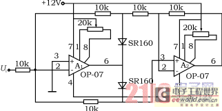
Figure 2 Absolute value amplifier schematic
3 frequency converter
The voltage-to-frequency converter is the core part of the battery capacity meter. It is responsible for converting the amplified signal into a frequency signal. Its linearity and accuracy directly affect the whole machine. There are also many ways to implement voltage-to-frequency conversion. Formally, there are two types of discrete components and special integrated chips. The accuracy, volume and adjustment complexity of general discrete components are higher than those of integrated chips, but the price is lower, while the dedicated chips are linear, voltage stable, Indicators such as accuracy are reduced relative to acceptable prices. Considering the volume and charge-discharge tracking and performance-price ratio, we chose VFC32 as the voltage-frequency conversion device. The better linearity of the device guarantees the tracking accuracy of the whole process, and the volume is reduced with fewer components. The circuit principle is shown in Figure 3.
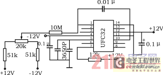
Figure 3 Schematic diagram of the frequency converter
4 reversible counter
The counters all use CMOS circuits. First, the power consumption is low. This is extremely important for power supply by the battery itself. Second, its level matches the load and discharge level, and the display range is increased. See Figure 4.
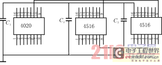
Figure 4 reversible counter schematic
A 14-stage pulse carry binary counter 4020 is used, and a 4-bit reversible binary counter 4516 is used to form a 21-stage counter. The high 7-bit counter value is valid as the count value and output, while the lower 14 bits are used only for counting and not for output, and 4020 is one-way counting, no subtraction function.
This design has two major advantages:
(1) The 4020 is a highly integrated counter that can be used in place of three and a half 4516, which greatly reduces the size.
(2) When adding, 4020 can be accurate to the lowest position; when subtracting, the error is lower fourteen, but this fourteenth bit is also the one-time maximum error, no accumulation, because the circuit uses asynchronous, synchronous Count the method of mixing. When 14 is subtracted (although 4020 is added), the 4020 output asynchronous pulse 4516 is decremented by "1" as if it were a true subtraction, and the value of 4020 is not output, which makes the result very accurate.
5 control circuit
This part contains preset circuits, anti-overflow circuits, and counting direction control circuits.
The prototype has a wide application range, and a toggle switch is added to the preset and control circuits of the counter, so that the initial value and the final value of the counting portion can be set by the toggle switch, and the purpose of detecting the use of the known battery capacitance can be achieved. Convenience.
At the same time, in order to prevent the counter from overflowing in two directions, the anti-overflow circuit is set separately, so that the counter will not count when it counts to zero and full value, in case of error.
By comparing the current flow directions, the output pulse controls the count of the up-down counter to form a direction control circuit.
6 display
There are two ways of displaying digital and pointer. In order to ensure an intuitive display, while using the instrument of an ordinary car as much as possible, the voltmeter indicating the battery voltage on the car is still used. It is more convenient to set a switch on the voltmeter to switch the voltage and capacity indications.
This requires converting the binary number of the counter to a voltage. Obviously, D/A conversion is possible, but the circuit complexity increases and the cost increases. Therefore, in order to simplify the circuit, we only borrow the idea of ​​D/A conversion network, and use the weight resistance T-shaped network to convert the 7-bit value of 4516 into an analog output, and push the voltmeter indication, as shown in Figure 5.
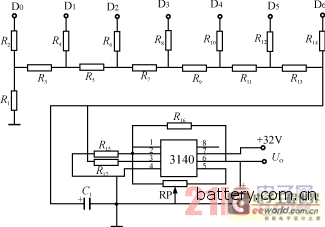
Figure 5 shows the circuit schematic
7 working power section
The battery capacity meter is different from other instruments in that it can only use the battery as the power source. Due to the change and fluctuation of the battery voltage, direct use is obviously not suitable. Therefore, the secondary power supply must be generated by the battery.
First, the Hall device requires ±12V power supply, and the circuit control count also borrows ±12V. In addition, we consider that in order to make the capacity indication more intuitive and clear, the maximum voltage range should be larger, and the voltmeter effective indication can be fully utilized. . The voltmeter range is 40V, and the battery voltage is up to 30V, so the maximum indication of the set capacity indication is 28V, which requires the power supply voltage to be 30V.
Because the battery has a large current discharge when starting, the voltage fluctuation is very strong, about 15 ~ 30V, in order to adapt to its changes, while reducing the power consumption of the capacity meter, improve efficiency, the design uses all switching power supply.
Firstly, the +12V is obtained by using the LM2575 buck regulator. The input voltage of the chip can reach 40V, the fixed oscillation frequency is 52kHz, and the voltage and current adjustment rate is good, which is suitable for the requirements of the capacity meter.
The -12V is converted from the input of +12V and converted by the 34063DC/DC converter. This loses some of the power. Our original design was introduced directly from the battery voltage with the M2575HV (input voltage 60V), but it was only due to the failure to buy the 60V LM2575HV. In the future, if there are batches, you can order them. Fortunately, the -12V power is limited and the loss is small. A set of 30V power supply, its high voltage, small current, such as the use of ordinary DC converters such as 2575 or other devices, the volume is too large, and the core components are so much waste, not worth the candle. Therefore, we have been looking for a concise method in the design. Finally, we decided to use the 555 oscillator to boost and use the voltage doubler rectification method to raise the 12V to 30V. The effect is very good, as shown in Figure 6.
Product design and calculation
Voltage/frequency relationship setting
Voltage 0~10V corresponds to frequency 0~10kHz
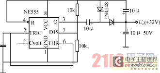
Figure 6 30V power supply schematic
Current 0~1000A corresponds to voltage 0~10V
The selection of these values ​​takes into account the optimum values ​​of the Hall element, amplifier, F/V conversion design and the needs of the test prototype.
2 count digits
4020-14 bit 4516 two pieces a total of 8 bits, add up to 22 bits, only 21 bits, the number of counts is:
221 = 2.097152 × 10⁶.
Counting time for 10 kHz
T = (221 × 1 / 104) seconds = 3.49 points.
When 10kHz corresponds to 1000A, for the 45Ah battery
T=C/I=45/1000=0.045h=2.7 points <3.49 points,
It can be seen that the timing is enough, and the full-time timing is
(221 × 1 / 104) × 1000 / 3600 = 58.25Ah.
3 error calculation
The first 14 levels of counting time are ΔT=214, totaling T=221, and the relative error ΔT/T=214/221=0.78%.
It can be seen that the error of the first 14 levels is extremely small, less than 1%, and it appears only once in the subtraction method and can be ignored. Therefore, it is reasonable to use a 4020 instead of three 4516.
Performance test result
The whole machine test, the condition is charging and discharging current 15A, voltage (representing capacity) indicates full capacity is 28.002V, after the battery capacity is exhausted, the voltage (representing capacity) is indicated as 0V, indicating the capacity and actual capacity error is 3%, in line with the design Claim.
In the mode where the output capacity is equal to the input capacity multiplied by the loss factor, this paper takes the electric vehicle as the object of use, and elaborates on the input sampling, absolute value amplification, voltage-frequency conversion, display and working power. A useful exploration is one of the effective methods for measuring battery capacity at present, and is suitable for a battery with no memory effect and relatively stable performance.
The spray dryer is a thermal process in which liquid materials are atomized into fine mist droplets through nozzles, which are in contact with the heating medium in the drying tower and are dried into powder. The feed can be a solution, suspension or paste. The atomization can be achieved through a rotary atomizer, a pressure atomization nozzle and an airflow atomization nozzle. The operating conditions and the design of the drying equipment can be based on the drying required for the product Features and selection of powder specifications.
Spray Dryer,Spray Drying Process,Spray Dryer Machine,Spray Drying Equipment
Griffin Technology Manufacturing Co., Ltd. , https://www.griffindryingeqpt.com
